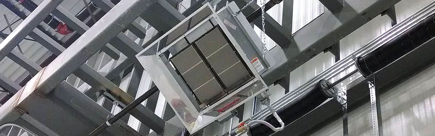

Low-Intensity Tube Heater
The low-intensity infrared tube heating system can reach up to 1300 degrees Fahrenheit emitting infrared energy to be absorbed by people and objects. This is accomplished by radiation (the primary way the heat travels) and conduction (heat transfer between objects and the air).
When properly applied, low-intensity infrared tube heaters are designed to be energy efficient and cost-effective for a wide range of commercial and industrial applications. Some of these applications include commercial warehouses, car washes, patios, and agricultural structures.
Our durable and reliable low-intensity tube heaters are effective in low bay areas and can be used for total building heat. Low-intensity infrared heaters can also be known as radiant tube heaters, positive-pressure tube heaters, tube brooder heaters, and stick heaters.
Contact your local rep to learn more about Solaronics' overhead radiant heaters and the accessories available.


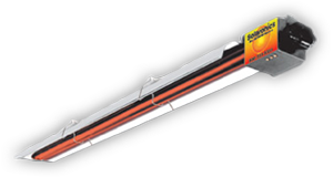
Low-Intensity Tube Heater Specifications
Solaronics’ Suntube low-intensity infrared tube heaters are powered by a positive pressure burner that fires into 4″ diameter by 5′ or 10-foot-long steel tubes. Burner ignition is accomplished by a pilotless direct spark. Combustion air is supplied to the system by a centrifugal blower and fixed air inlet orifice.
A standard 4″ diameter inlet air collar allows for connection to outside air without the use of supply fans. The system is approved for either directly vented or indirectly vented operation without the use of a vacuum pump.
The power burner along with the combustion chamber, heat exchangers, and reflectors comprise the entire heater. These heaters are CSA International Designed and Certified to ANSI/CGA Standards.
True Dual
Our Two-Stage True Dual Series provides precise air to gas ratios for high-low heat stages, for optimum efficiency.
Learn More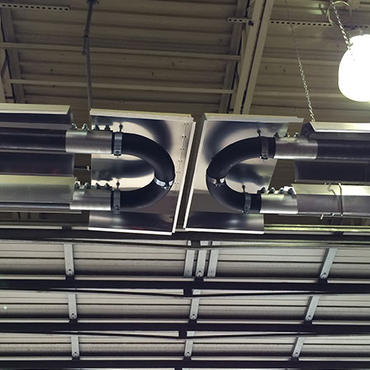
Low Intensity Accessories
Add on items for increased efficiencies and simplified installations.
Learn More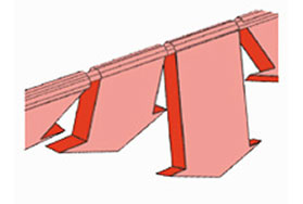
Low Intensity Reflectors
Superb reflectional efficiency precisely directs infrared where you want it.
Learn More
Combustion Chamber / Heat Exchanger
With our 16 gauge tube options, we have the right type for your application.
Learn More
How Does a Low-Intensity Tube Infrared Heater Work?
The low-intensity burner utilizes a 1/25th HP, 120V AC single phase-60Hz motor and centrifugal blower which provides 148 CFH free air with a 1.47 full load AMP draw on A & B Series and 138 CFH free air with a 1.33 full load AMP draw on C Series. A fixed air orifice plate regulates the appropriate air required for combustion. Gas is introduced to the burner by a two-stage redundant gas valve.
Gas is then regulated by two orifices, an easily accessible subsidiary orifice sized for the appropriate length and BTUH rating of the burner, and a fixed main orifice. Air and gas are thoroughly mixed in a spiral motion by the burner core assembly and are then ignited by a direct spark at the ignition module.
Burner operation is monitored and controlled by an ignition detection control. When the thermostat calls for heat, power is applied to the blower motor. A dual airflow switch continuously monitors the air supply. When adequate inlet air and flue back pressure are present, the ignition detection control is energized and institutes a 15-second pre-purge cycle. This is followed by a 35-second trial for ignition during which a spark is developed at the ignition module and the gas valve is opened to the first step of its two-stage operation. Gas is then ignited and approximately 5 seconds later the gas valve stages to its second and final operation position. A flame rod, part of the ignition module senses a flame presence and the ignition detection control shuts off the spark current and monitors continued flame presence. Should flame failure, blocked flue or blocked inlet air occur during ignition or normal operation, the ignition detection control will close the gas valve and lock out the system. The system will remain locked out
Three system monitoring lights indicate normal burner operation. When lit, these monitoring lights indicate normal conditions for power on; inlet air and flue back pressures; and gas valve on. A burner inspection sight glass also allows for visual inspection of the flame and ignition module.